Muzzle brakes that don't blow off

grit

Well-Known Member
Joined
Mar 23, 2005
Messages
1,375
Location
Utah
After the recent thread, I figured many would enjoy seeing how brakes are installed. I'm installing one now. I'll offer some photos and explanations. If you have any questions, I'd be happy to answer.

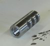
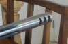
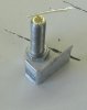
For starters, here is a finished brake, blended and polished to match the factory Sendero barrel. I built this brake to suit the customers wants.
 

Attachments

  • brake-flush.JPG
    brake-flush.JPG
    27.9 KB · Views: 170
Here, I have a barrel through the headstock of the lathe, preparing to install a brake.
 

Attachments

  • brake-lathe.JPG
    brake-lathe.JPG
    39 KB · Views: 157
Here's a closer view. I have cut an inch off the barrel, and refaced the end. I cut from the center out to not push a burr into the bore. This is important for the indicator rod. You will notice aluminum L's between the chuck jaws and barrel. I have finished dialing the barrel in. I start with a .001 indicator, and finish with a .0001 indicator. I indicate in two places on the rod to dial in both ends of the barrel.
 

Attachments

  • brake-dial.JPG
    brake-dial.JPG
    37.5 KB · Views: 113
Here is the indicator rod with removable bushing. The rods are tapered. You choose a bushing to precisely fit the bore, then slide the rod in until the taper stops it. It is critical there are no burrs on the bore, and the bore is clean. There are several ways to dial in. They all work if you understand the possible shortcomings.
 

Attachments

  • indicator.JPG
    indicator.JPG
    14.7 KB · Views: 104
Here is the outboard end of the head stock. The four opposing screws are called a spider. This allows both ends of the barrel to be dialed in. The barrel has an aluminum collet around it to prevent marring, and to aid dialing. The action is temporarily installed to mark the top flute, for brake timing.
 

Attachments

  • brake-spider.JPG
    brake-spider.JPG
    42.5 KB · Views: 155
Here is a photo of the aluminum L's in the chuck. These allow the barrel to pivot when dialing in, and prevent slipping and marring. The brass tipped screws (they are .22 shells) are in the spider. This makes for a short pivot point, prevents marring, and aids dialing.
 

Attachments

  • shim-screw.JPG
    shim-screw.JPG
    31.3 KB · Views: 106
This is the brake the customer supplied. I believe it is from Center Shot Rifles. The next steps are to turn the barrel to diameter, thread the barrel, time the brake, recheck our dial in, cut the barrel crown, install the brake, drill the brakes bore hole, double check our bore hole alignment and size, chamfer the edges, cut the taper on the brake, blend the brake, and bead blast. If that isn't a run-on sentence... As you can see, some thoughtful person labeled the top of the brake to keep the gunsmiths world right side up :D.
 

Attachments

  • CSR-brake.JPG
    CSR-brake.JPG
    25.3 KB · Views: 129
I forgot two steps. Gotta feed the horses and get a pepsi :D. I'll photograph and post more as I go.
 
In the first photo, I've taken a light pass and set a micrometer stop a few thousandths short of my desired tenon length. When I get to diameter, I'll back the stop off a few thousandths and pull the cutter out for a nice shoulder. The second photo is turned to the correct diameter.
 

Attachments

  • turning.JPG
    turning.JPG
    53.6 KB · Views: 127
  • turned2.JPG
    turned2.JPG
    42.1 KB · Views: 113
I've taken a light threading pass and am verifying my thread pitch is correct.
 

Attachments

  • initial-pass.JPG
    initial-pass.JPG
    35.9 KB · Views: 153
I set the compound the same angle as the threads. Advancing the thread depth with the cross slide minimizes cutter contact and chatter, for a smooth thread cut. This is my first test fit. The brake just starts to thread. From this point I will advance the crosslide, rather then the compound, .001 per pass until the brake threads on completely. The goal is resistance free threading with minimal clearance.
 

Attachments

  • test-fit.JPG
    test-fit.JPG
    34.4 KB · Views: 126
I took .003 from the first test, where it started to thread, to final thread depth. Out of curiosity, I put an indicator on the brake. With the brake threaded on half way there is .002 movement at the indicator. If you did the math, you might figure there is under .001 play in the thread fit. You could shoot the rifle like this without clearance issues or the brake blowing off.
 

Attachments

  • threaded.JPG
    threaded.JPG
    39.2 KB · Views: 117
Warning! This thread is more than 12 years ago old.
It's likely that no further discussion is required, in which case we recommend starting a new thread. If however you feel your response is required you can still do so.
Top